
Digital Twin for Rapid Thermal Processing: Fault Detection and Diagnostics
This case study shows how a physics-based digital twin (DT) can be used to detect and diagnose sensor and actuator faults during rapid thermal processing (RTP) of semiconductor wafers, supporting predictive maintenance and helping fabs avoid costly unplanned downtime.
Background
In semiconductor manufacturing, a digital twin is a fast, physics-based software model that runs alongside a piece of equipment (its physical twin) and is continuously updated with sensor data from the process, as illustrated in Figure 1 [1]. The goal is not to reproduce every detail of the hardware, but to capture the key dynamics accurately enough to support fault detection, performance assessment, and, ultimately, predictive maintenance.
Digital twins are beginning to improve the performance and reliability of semiconductor manufacturing equipment, including Rapid Thermal Processing (RTP) tools used in several key steps of wafer fabrication. Yield loss in chip manufacturing can result from sensor failures, actuator (lamp) failures, gas-flow failure, or sensor drift, and identifying the root cause of such problems can be challenging. A physics-based DT can provide the insight needed for operations ranging from fault detection to predictive maintenance.
This case study examines how far a physics-based DT can go toward diagnosing faults in an RTP tool. We consider two classes of problems:
- Sensor fault detection, an area that is relatively mature and can be handled effectively with a bank of Kalman filters, and
- Actuator (heating lamp) fault detection, which is more challenging because the thermal effects are distributed and strongly coupled across the wafer.
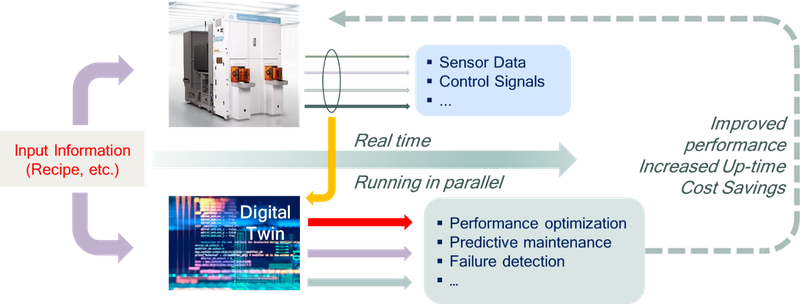
Figure 1: Schematic of a digital twin deployed for semiconductor process equipment.
Rapid Thermal Processing (RTP)
RTP systems are used for several high-temperature wafer processing steps, including implant anneal, dopant activation, silicide formation, and thin dielectric processing. In RTP, a wafer is heated rapidly to a process temperature and then cooled along a prescribed trajectory. For implant annealing, silicon wafers are heated to about 1050°C in a few seconds followed by rapid cooldown — a heat treatment that relieves the stresses of ion implantation and activates the implanted dopants to form the transistor junctions in the finished chip.
The process requires that temperature non-uniformity remain below 5°C–10°C during ramp-up and cooldown, and below 1°C during processing, across the full 300-mm wafer surface. This tight uniformity is needed to prevent warping or crystal slip in a wafer that is less than 1 mm thick. Even if the temperature is held uniform at the handful of measurement locations, the temperature elsewhere on the wafer could drift far from the target and warp the wafer. A DT built on a physics-based model acts as a virtual sensor, monitoring temperatures across the entire wafer and helping the controller maintain tight uniformity everywhere — not just at the few measured points.
SC Solutions has decades of experience in RTP modeling and control, and licensing this control software to OEMs is a core part of our business. The generic RTP chamber described below shows how that modeling foundation extends naturally into a digital twin for monitoring and diagnostics.
Modeling and Control for RTP
Figure 2 shows a generic RTP chamber geometry that captures the key elements of commercial RTP systems, with simplifications such as axial symmetry. The chamber contains multiple lamp rings above the wafer, highly reflective cooled walls, and quartz components that transmit the short-wavelength radiation used to heat the wafer and guard ring. A physics-based thermal model predicts the nonlinear, transient temperature distribution across the chamber and forms the core of the digital twin.
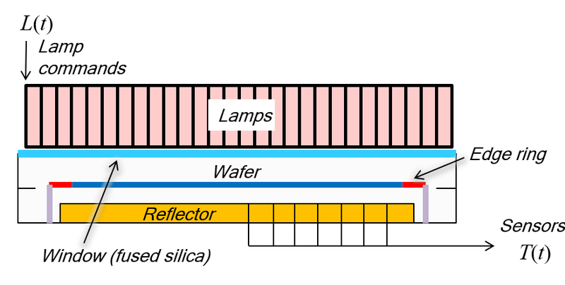
Figure 2: Cross-section of a generic RTP chamber, showing the lamp array, wafer, edge ring, and sensor locations.
Building a model that is both accurate and runs faster than real time is challenging. Radiative transfer, the dominant heat transfer mode in RTP, is strongly nonlinear in temperature, and RTP spans a wide operating temperature range. A sufficiently accurate radiative model is typically computationally intensive that can be slow to run — yet the DT must operate faster than real time. SC Solutions has developed the methodology needed to build low-order dynamic models that run fast while remaining accurate enough for precise temperature control and virtual sensing.
Because the lamps heat overlapping areas of the wafer, RTP control must account for interaction among lamp zones rather than treat each zone independently. This interaction makes RTP a multi-input multi-output (MIMO) control problem. The chamber also contains components with very different thermal time constants. Lamp filaments respond quickly to changes in power, while quartz components such as the window respond much more slowly. This spread in dynamics makes closed-loop control essential for achieving the tight requirements imposed by IC fabrication.
A multivariable feedback controller can follow the desired temperature trajectory, reject disturbances, and respect actuator limits and be robust to system changes. In our RTP work, Linear Quadratic Gaussian (LQG) control has proven most effective because it naturally handles multivariable interactions, measurement noise, and integral action within a single framework [2]. Figure 3 (left) shows this closed-loop framework, and Figure 3 (right) compares the model-predicted wafer temperatures and lamp commands with data from a commercial RTP tool. The excellent agreement makes the model useful not only for control design, but also for digital-twin-based monitoring and diagnostics [2].
![Figure 3: Left: Closed-loop control architecture for RTP. Right: Comparison of model-predicted wafer temperatures and lamp commands (Simulation Model) with data from a commercial tool (Process Data) [2].](https://scsolutions.com/wp-content/uploads/figure-3-rtp-closed-loop-control-comparison.png "figure-3-rtp-closed-loop-control-comparison")
Figure 3: Left: Closed-loop control architecture for RTP. Right: Comparison of model-predicted wafer temperatures and lamp commands (Simulation Model) with data from a commercial tool (Process Data) [2].
A Digital Twin for RTP Diagnostics
For RTP equipment, a digital twin can support several functions such as monitoring process performance, detecting sensor and actuator faults, estimating hidden or inaccessible states (virtual sensing), and providing information essential for predictive maintenance.
This case study focuses on fault detection, isolation, and recovery (FDIR), covering two categories: sensor faults, detected with a bank of Kalman filters (BKF), and actuator faults, detected with a disturbance observer (DO). A third category, parameter excursions caused by drifting material properties, is harder to diagnose because it often influences the process only indirectly, and is not discussed here.
To evaluate these methods, we built a simulation environment that mimics an RTP tool operating in closed loop, shown schematically in Figure 4. The plant, actuators, and sensors are represented by the physics-based RTP model described above. A model-based MIMO feedback controller drives the system using noisy temperature measurements, while the digital twin runs in parallel in real time, receiving the same inputs and measurements and applying diagnostic logic to determine whether the observed behavior is consistent with normal operation or with a fault.

Figure 4: Digital twin framework for fault detection, isolation, and recovery (FDIR) in RTP.
Sensor Fault Detection Using a Bank of Kalman Filters
A bank of Kalman filters is a practical way to detect sensor faults [3]. A Kalman filter is a running estimate of the system’s behavior. At each instant of time, it blends what the model predicts should happen next with what the sensors actually report, weighting each according to its expected noise. In a bank-of-filters approach, several such estimators run in parallel, each representing a different fault hypothesis, as shown in Figure 5. The hypothesis whose prediction best matches the measurements, points to the most likely faulty sensor.
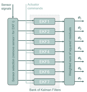
Figure 5: Schematic of a bank of Kalman filters for sensor fault detection.
Using SC Solutions’ low-order RTP model, we built a bank of Kalman filters for seven temperature sensors. Figure 6 shows a representative case in which a large bias (−100°C) is introduced into one sensor; the digital twin correctly identifies the faulty sensor and supports recovery by substituting an estimator-based virtual measurement. There are two significant observations here. First, the digital twin can identify which sensor is inconsistent with the rest of the system. Second, once a fault is isolated, the estimator (model) can generate a “virtual” measurement so that the process can continue safely until maintenance is performed.

Figure 6: Sensor fault detection and accommodation using a bank of Kalman filters — detection of a −100°C fault on Sensor #2.
Actuator Fault Detection Using a Disturbance Observer
Actuator fault detection is addressed using a disturbance observer. The idea is straightforward: the digital twin estimates how much heat the lamps should be producing based on the commanded power, and compares that expectation with what the wafer temperatures indicate is actually happening in the chamber, as shown in Figure 7. The difference behaves like an estimated disturbance. When interpreted carefully, it can reveal a loss of actuator effectiveness.

Figure 7: Block diagram of a disturbance observer used together with the standard temperature controller.
This problem is harder than sensor fault detection because the RTP chamber in this study has fourteen heater zones but only seven temperature sensors, so the available measurements do not directly reveal every actuator’s condition. Good calibration and an accurate nonlinear model for the DT are therefore essential when a disturbance observer is used to detect actuator failures.
Our studies show that the disturbance-observer approach is effective, with both strengths and limitations:
- Large actuator losses can be detected reliably, including partial and full loss of lamp power.
- With a well-calibrated nonlinear model, the method can infer more about actuator health than the raw sensor count alone would suggest, because the physics-based model captures the strong thermal coupling across the wafer.
- Even when isolation is incomplete, the disturbance estimate still provides useful maintenance information.
- Measurement noise affects detection thresholds and sensitivity.
- Model uncertainty and unrelated parameter changes can appear similar to actuator faults if calibration is poor.
- Recovery logic — deciding what to do once a fault is detected — is application-specific and generally harder to design than detection alone.
Benefits
This case study demonstrates that a fast, physics-based digital twin can support effective fault detection for RTP equipment today, particularly for sensor faults and larger actuator losses. Sensor-fault detection using a bank of Kalman filters is a relatively mature technique, and actuator-fault detection using a disturbance observer can reliably flag large losses of lamp power even with limited sensor coverage. In both cases, the DT provides virtual sensing — supplying a trustworthy estimate in place of a failed measurement so that production can continue safely until maintenance is scheduled and performed.
These capabilities support the broader promise of DT for predictive maintenance of semiconductor wafer-processing equipment, helping engineers catch emerging faults before they cause unscheduled downtime. The key requirement is a dynamic model that is both fast, running faster than real time, and accurate enough for nuanced interpretation of the process. SC Solutions’ physics-based modeling and control expertise, developed over decades of RTP work, provides such models appropriate for use in digital twins.
Please contact us if you would like more information regarding digital twin development for RTP or other semiconductor process equipment.
References
- S. Ghosal, D. de Roover, and A. Emami-Naeini, “Digital Twins – Concepts, Uses, and Adoption in Industry,” News and Views, SI Solutions’ annual technical magazine, Vol. 55, p. 28, 2025.
- J. L. Ebert, D. de Roover, L. L. Porter II, V. A. Lisiewicz, S. Ghosal, R. L. Kosut, and A. Emami-Naeini, “Model-Based Control of Rapid Thermal Processing for Semiconductor Wafers,” Proc. American Control Conference, pp. 3922–3929, June 2004.
- Y. Liu, X. Qian, and H. Zhang, “Sensor Fault Detection Using Kalman Filter Bank and Dynamic Modeling of Sensors,” Sensors, 13(3): 3311–3329, 2013.