Thermal Model of MOCVD Chamber
case studySC Solutions develops physics-based models of chambers for Metal-Organic Chemical Vapor Deposition (MOCVD). Our capability is illustrated here using an example from the literature (U.S. Patent 8778079).
Background
MOCVD is a deposition technique used to grow thin films on solid substrates (wafers) using organo-metallic compounds as sources. The films grown by MOCVD are usually semiconductors and are primarily used for the fabrication of electronic and optoelectronic devices that are components of cell phones , optical communication, optical storage, light emitting diodes (LEDs), and solar cells. MOCVD is used to build up multiple layers of different materials, each of a precisely controlled thickness, to engineer a material with desired optical and electrical properties.
FEM Model of Chamber
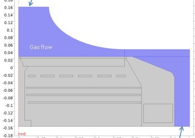
SC built a FEM model of the chamber described in U.S. Patent 8778079 using COMSOL software. The figure below shows a cross sectional view of the chamber and other components. A two-dimensional (2D) axisymmetric FEM model of the chamber with a rotating susceptor was developed. The model incorporates gas flow, and conduction and radiation heat transfer throughout chamber. The gas below the susceptor is nitrogen while the gas in the chamber above the susceptor is hydrogen. The six tungsten heaters below the susceptor are connected to three power supplies, with middle four heaters grouped together.

A two-dimensional (2D) axisymmetric FEM model of the chamber with a rotating susceptor was developed. The model incorporates gas flow, and conduction and radiation heat transfer throughout chamber. The gas below the susceptor is nitrogen while the gas in the chamber above the susceptor is hydrogen. The six tungsten heaters below the susceptor are connected to three power supplies, with middle four heaters grouped together.
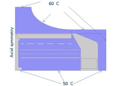
For baseline case, we used hydrogen flow at 150 standard liters per minute (slm) at inlet. The bottom cooling plate was kept at 50°C. The upper boundaries, including the inlet, and the vertical boundary surface of the chamber were assigned a temperature of 60°C. The susceptor rotation speed was specified to be 800 RPM, and the chamber pressure was 500 torr. The susceptor is heated by tungsten filaments primarily by radiative heat transfer.
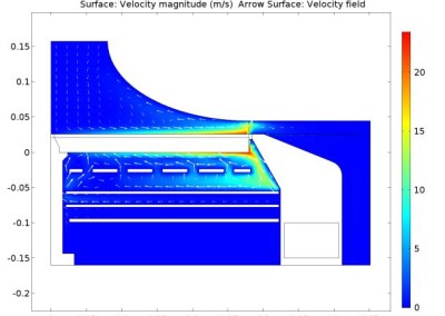
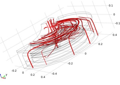
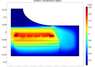
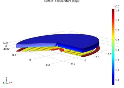
A steady-state simulation of this model runs fast on a typical workstation, typically in less than a minute. The two sets of figures below show some results. The flow profile shows recirculation cells in the MOCVD chamber. Arrows show u and v velocity components. The streamlines in the three-dimensional schematic show swirl flow due to wafer rotation. The temperature plots show that the innermost and the outer heaters have to be run at higher power settings compared to the middle four heaters (which are grouped together) to compensate for losses to the support and at the edge, respectively.

Temperature gains were computed with a 5% change to the power density to each of the three power zones. The graphs on left show the temperatures of the top surface of the susceptor vs. radial distance. Using these gains, optimal power settings were determined for the three heater zones for maximizing temperature uniformity on the part of the susceptor where the wafers are located (50 mm ≤ R ≤ 225 mm) at process temperature of 1100°C. With optimal power input, the temperature uniformity is found to be within 1°C as seen in the figures below.

Benefits
Physics-based MOCVD models are useful in many ways including model-based control, design of next-generation chambers, virtual sensing and process optimization. If you would like more information regarding physics-based model development and its application to your system, please contact us here.
